
Introduction
Have you ever wondered why some labs get clean, repeatable neural signals while others wrestle with noise and drift? The scene I see often is a busy bench, a tangle of cables, and a dataset that needs rescue — and the numbers show it: many groups report up to 30% unusable recordings due to hardware or workflow issues. A fiber photometry system sits at the center of that mess, controlling light delivery, detection, and the timing that makes experiments meaningful. (I approach this cautiously — think like a cybersecurity analyst scanning for weak points: where does the signal leak, and how do we close the gaps?)

In this piece I’ll compare real trade-offs, point out where common setups fail, and ask the practical question: which system choices actually save time and protect data quality? Let’s move from symptoms to causes — and then toward smarter options.
Hidden User Pain Points in rwd fiber photometry
rwd fiber photometry often gets praised for flexibility, but I’ve seen installation and workflow problems hide in plain sight. Technical factors like gain control, analog-to-digital converter settings, and LED excitation timing are easy to overlook during setup. When these are off, you lose dynamic range or introduce artifacts that mimic biological events. I’ve spent late nights troubleshooting why a trace looked like a spike train — and it turned out to be a synchronization issue between the photodetector and the DAQ. Look, it’s simpler than you think: small mismatches create big headaches.
Many users assume optical fiber connections are plug-and-play. They are not. A loose connector, stray ambient light, or improper patch-cord polishing can change your signal-to-noise ratio dramatically. I recommend testing each link in the chain: LED, fiber, photodetector, and the power converters that feed the electronics. In my experience, groups that instrument a basic bench checklist cut failed trials by half. Also — funny how that works, right? — training and simple SOPs beat fancy automation when staff turnover is high.
What’s the most common overlooked setting?
Calibration routines and reference runs. Many skip a brief calibration before each session and then wonder why baselines drift. It’s a small time investment that pays off in reliable data.
New Technology Principles and a Practical Comparison
Moving forward, I favor principles that prioritize deterministic timing and modular diagnostics. New designs for fiber photometry emphasize locked timing between LED pulses and acquisition to prevent bleed-through and to improve demodulation. When we combine stable LED drivers, clean analog front-ends, and a clear synchronization protocol, we reduce false positives and make analysis easier. In practice I compare setups by how well they isolate variables: can I change LED intensity without re-tuning the entire system? Can I swap a fiber patch cord and rerun a quick self-test? These are the measures that matter in the lab.
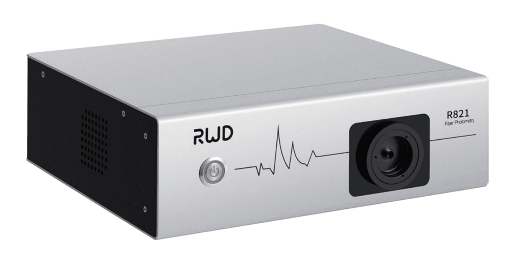
I’ll mention rwd fiber photometry again because it illustrates modular design: multichannel capability with per-channel gain and timing controls helps when you run complex stimulation protocols. Semi-formal and practical — that’s how I describe the next-gen approach. Also, consider integrating simple edge computing nodes to preprocess and flag bad trials in real time; that reduces wasted storage and analysis time. The principles are straightforward: isolation, synchronization, and modular diagnostics — apply them and you’ll see fewer surprises.
What’s Next?
Here are three practical evaluation metrics I use when choosing or upgrading a fiber photometry solution:
1) Timing precision: Does the system guarantee microsecond-level synchronization between LED excitation and acquisition? I insist on this because timing errors create ambiguous events. 2) Diagnostic transparency: Are there built-in tests for fiber integrity, photodetector response, and baseline drift? I want visible checks, not opaque black boxes. 3) Modularity and serviceability: Can I replace a driver, swap a photodetector, or update firmware without halting other channels? Downtime costs real money and experiments — so pick systems designed for quick fixes.
To wrap up: I’ve seen the same core problems across labs — and the fixes are practical, not mystical. If you focus on synchronization, clean analog paths, and modular diagnostics you’ll cut noise and lost trials. Weigh choices against the three metrics above and you’ll make smarter purchases that save time and protect your data. For more detailed specs and real-world setups, I often look to providers who document diagnostics clearly — like BPLabLine.