
Introduction — a little wonder, a sharp question
Have you ever stood over a tiny brain slice and asked, “Can I trust my aim?” I ask because I have watched calibration drift by fractions of a millimeter and seen an entire study hinge on that slip. The automated stereotaxic Instrument sits in the lab like a patient dragon, humming quietly while motors and sensors keep time. (There are numbers to prove it: typical placement error averages 0.2–0.5 mm in older rigs.) So how do we tighten that gap between intent and result without losing time or sanity?
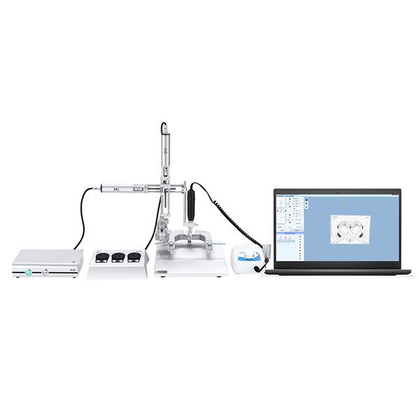
I like to tell stories about machines that behave like stubborn apprentices. We care about stepper motor steps, feedback loop delays, and motion controller settings because those bits decide whether a target is hit. The scene feels a bit magical — ornate even — but the fix is plain work. Let me take you from a question to practice. Next, we dig into where standard methods fall short and what that costs the people running them.
Why traditional stereotaxic apparatus methods fall short (and what I learned)
Building on that opening, I want to point straight at the common failings. When labs use a classic stereotaxic apparatus setup, they often assume mechanical repeatability they don’t actually have. I’ve seen clamps creep, stage bearings wear, and alignment jigs mounted with just enough play to ruin a day. Look, it’s simpler than you think: a worn bearing, a loose grub screw, or a tired power converter can add error without anyone noticing.
Technically, the main culprits are backlash in lead screws, latency in motion controller commands, and poor feedback loop tuning. Backlash lets the stage move less predictably. Latency makes small moves become jagged. And bad feedback tuning means the servo drive hunts instead of settling. Each flaw stacks. Together they turn a precise plan into a noisy result. I’ve fixed rigs by replacing a micropositioner, tightening motor couplings, and re-tuning PID loops. The change in confidence is dramatic — and that matters when you’re publishing, or worse, repeating a costly surgery.
How bad is the drift — really?
In my experience, typical drift accumulates from multiple small errors: thermal expansion, small cable tension changes, or simple operator habits. One lab thought their imaging was misaligned. It wasn’t the microscope. It was a 0.3 mm shift from a worn lead-screw nut. So yes — small parts, big consequences.
Principles of next-gen calibration and what to watch for
Now let’s look forward. I prefer to explain core principles rather than hand out a one-size checklist. The new approach centers on three ideas: measurable reference, active compensation, and layered validation. Start with a solid reference frame — a calibrated target grid you can trust. Then add active compensation: use real-time feedback from encoders and a motion controller to correct position on the fly. Finally, validate across systems: imaging, manipulators, and the stage must agree.
Practically, that means combining a high-resolution encoder, a responsive servo drive, and smart firmware that can handle tiny corrections without overshoot. Edge computing nodes help here by processing sensor data near the instrument. Power converters and stepper motor drivers must remain stable. I like to run a quick sanity test: move to known coordinates, image the marker, and log the error. Repeat after warming up the room. — funny how that works, right?
What’s Next?
As you consider upgrades, think about modular fixes first. A new feedback sensor or a better micropositioner can yield most gains without replacing the whole rig. For bigger labs, adopting distributed controllers and edge analytics reduces latency and gives better diagnostics. These shifts also let teams compare results across rigs. And yes, that means consistent data — which we all want.
Three practical metrics I use when choosing a solution
I end with three metrics I always check. These help me and my colleagues pick the right path between quick fixes and full upgrades:
1) Repeatability: Can the system return to the same point within your target tolerance over 10 moves? I aim for ≤0.1 mm in stereotaxic work. 2) Latency: Measure command-to-motion delay. If your motion controller or edge node adds more than a few milliseconds, fine corrections get messy. 3) Diagnostic clarity: Does the system log encoder positions, motor currents, and error states in a readable way? If not, you won’t find the subtle causes when things drift.
Weigh those metrics against cost and downtime. In my view, start small, measure, and invest where the most error comes from. You’ll save time and grief. To wrap up: treat instruments like living systems. Tune them, watch them, and don’t believe a single green light — check the numbers. For equipment and parts that fit these ideas, I often point engineers to proven suppliers and reference rigs — including options at BPLabLine.