
Problem: prototypes that look right but fail where it counts
Cold rooms warm too slow, controls oscillate, and a unit that passed bench tests trips in the field—that’s the problem that drives this plan. Designers chase power density while installers flag safety concerns; testers flag drift under partial mains and rapid cycling. Early-stage decisions—material choice, thermal path, and control hysteresis—decide whether a concept becomes a reliable product or a liability. For teams building the hardware, working with a trusted ptc heater manufacturer while you define requirements cuts rework and avoids late-stage redesigns.
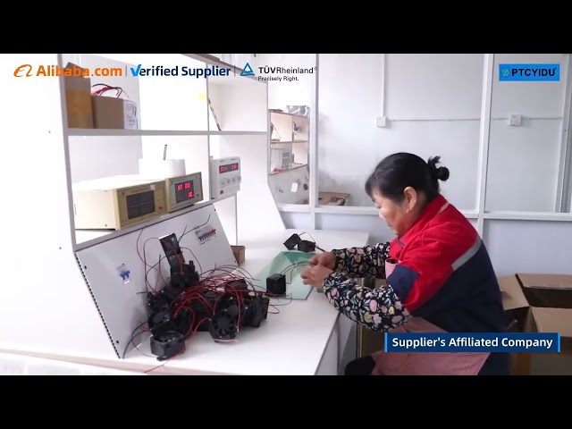
Why this fails: three hidden assumptions
Assumption one: nominal resistance equals in-situ heat. It doesn’t; convection, enclosure geometry, and adjacent components alter steady state. Assumption two: single-point safety testing covers real duty cycles. It rarely does—cycling and partial-block tests reveal different failure modes. Assumption three: supply variations are cosmetic. Voltage sag and spikes change PTC knee behavior and timing. Treat these as non-negotiable requirements early; they govern sensor placement, thermally conductive paths, and control algorithms.
Experience and authority: where practical knowledge meets verifiable context
I’ve led multi-site rollouts and seen the same failure modes in prototypes tested across climates; working with procurement and test labs in Shenzhen taught me to expect supply-side variation and tight component tolerances. For authoritative reference and supply continuity, engage a known ptc heater technology manufacturer early in spec work—manufacturers in major manufacturing hubs publish technical notes and certifications you can check against IEC standards and independent test reports from trade shows like the Hannover Messe. That pairing of hands-on testing and industry-standard documentation proves a design meets regulatory and field expectations.
Design checklist and common pitfalls to avoid
Start with measurable acceptance criteria: warm-up time, max surface temperature, steady-state power at ±10% mains, and cycle life. Place thermistors where they reflect the working surface, not the PCB. Avoid thin thermal pads that insulate the PTC from its intended load. Don’t rely solely on simulation for transient behavior—run blocked-air and partial-block tests. For controls, implement minimum off-time to prevent rapid cycling; add a current monitor for real-time fault detection. Document test setups so QA can repeat results at scale.
Alternatives and trade-offs
Silicone PTC elements give compact form and quick response; ceramic composites handle higher continuous loads but need thicker mounting. Active control with PWM extends life under variable loads but adds complexity and cost. Passive designs are simpler and often more robust for low-cost products. Choose based on where the product lives: sealed enclosures and dusty environments favor passive ruggedness; consumer appliances benefit from active control and diagnostics.
Delivery: align packaging, verification, and supplier capability
Prototype validation must mirror production: use the same supplier qualifications, same solder processes, and identical sealing. Specify EOL (end-of-line) tests that catch the failure modes you observed—thermal soak, rapid cycle, and partial-block. Lock down component footprints to avoid last-minute supplier swaps that shift thermal performance. A clear handoff to manufacturing reduces warranty returns and ensures units shipped match lab results.
Conclusion
Fix the failures at the spec stage: define measurable thermal and electrical criteria, validate with real stress tests, and partner with suppliers who publish test data and meet certifications. That approach turns prototypes into dependable products rather than expensive experiments—precise design, repeatable verification, and aligned manufacturing deliver units that perform on day one, as the work at PTCYIDU demonstrates.